You use the Tolerance Policy Editor to enter tolerance and roughness values for all GCDs in a component, and to control the import of PMI attributes from the CAD model.
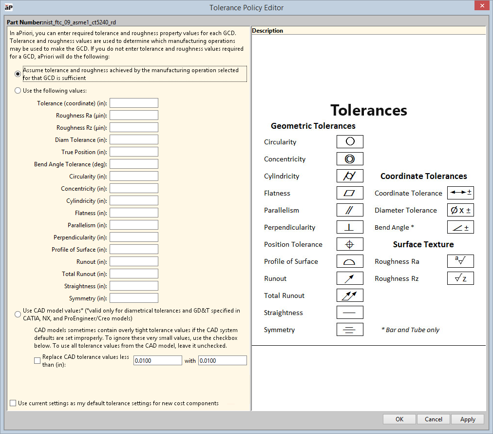
The Tolerance Policy Editor allows you to set tolerance and roughness values and behavior.
It also shows a reference panel showing common drafting symbols for supported tolerance and roughness specifications.
To manually set individual tolerances, use the Tolerance Editor - see Manually Edit Tolerance Values.
Edit Tolerance Values
-
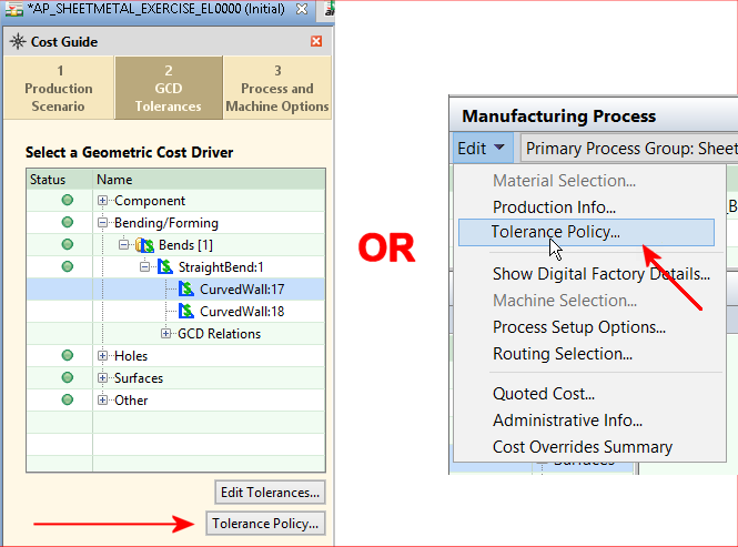
Open the Tolerance Policy Editor:
-
From the GCD Tolerances tab of the Cost Guide
-
From the Edit menu in the Manufacturing Process panel
-
-
Enter values in the Editor as needed
-
Assume tolerance and roughness achieved by the manufacturing operation selected for that GCD is sufficientoption is the default. If you do not set or import values, aP Pro assumes the processes have enough tolerance capabilities to manufacture the GCD, and assigns a tolerance of unspecified. If you do set or import specific values, aP Pro analyses tolerance and roughness capabilities during routing and operation sequence selection. See Edit Geometric Cost Drivers for details.
-
Use the following values - select this to manually define tolerances, adding values for the tolerance and/or roughness settings you want to control for the part. These values are used for each GCD that does not have values manually set at the GCD level. See How Tolerances Map to GCDs for information about specific settings.
- Use CAD model values: Set aP Pro to use the tolerance and roughness specified by semantic PMI attributes in the CAD model.
- Replace CAD tolerance values less than: If the CAD model has overly tight tolerance values, which can occur if tolerance defaults are set by CAD PMI imports, select the checkbox then enter a limit for the overly tight tolerance values, and enter a replacement value.
-
-
Use current settings as my default for new cost components (visible after making any changes) Use the current tolerance policy settings as the default settings for all future (new) cost components.
-
Click OK to apply changes, recalculate the cost, and close the Tolerance Policy Editor, or click Apply to apply changes and recalculate the cost without leaving the Tolerance Policy Editor.
How Tolerances Map to GCDs
Each tolerance and roughness type applies only to certain GCD types. The following table which shows what types of tolerance apply to each GCD type, and whether they can be imported as PMI from CATIA, Creo, NX™, and SOLIDWORKS™.
|
|
Symbol |
Curved Surface |
Curved Wall |
Keyway |
Planar Face |
Simple Hole |
Complex Hole |
MultiStep Holes |
Edge |
Bend (B&T) |
Lance |
Import from PMI? |
|---|---|---|---|---|---|---|---|---|---|---|---|---|
|
Tolerance (coordinate) |
|
X |
X |
X |
X |
X |
X |
|
X |
|
X |
N |
|
Roughness Ra |
|
X |
|
|
X |
X |
|
|
|
|
|
Y, except SOLIDWORKS™ |
|
Roughness Rz |
|
X |
|
|
X |
X |
|
|
|
|
|
Y, except SOLIDWORKS™ |
|
Diam Tolerance |
|
X |
X |
|
|
X |
|
|
|
|
|
Y |
|
True Position |
|
X |
X |
|
X |
X |
|
|
X |
|
X |
Y |
|
Bend Angle Tolerance |
|
|
|
|
|
|
|
|
|
X* |
|
N* |
|
Circularity |
|
|
X |
|
|
X |
|
|
|
|
|
Y |
|
Concentricity |
|
|
X |
|
|
X |
|
|
|
|
|
Y |
|
Cylindricity |
|
|
X |
|
|
X |
|
|
|
|
|
N |
|
Flatness |
|
|
|
|
X |
|
|
|
|
|
|
Y |
|
Parallelism |
|
|
X |
|
X |
X |
|
|
|
X |
|
Y |
|
Perpendicularity |
|
|
X |
|
X |
X |
|
|
|
|
|
Y |
|
Profile of Surface |
|
X |
X |
|
X |
|
|
|
|
|
|
Y |
|
Runout |
|
X |
X |
|
X |
X |
|
|
|
|
|
Y |
|
Total Runout |
|
X |
X |
|
|
X |
|
|
|
|
|
Y |
|
Straightness |
|
|
X |
X |
X |
X |
|
|
|
|
|
Y |
|
Symmetry |
|
X |
X |
X |
X |
X |
|
|
|
|
|
Y |


* CAD Angularity GD&T callout maps to Bend GCD in Bar & Tube only. Entered manually only.